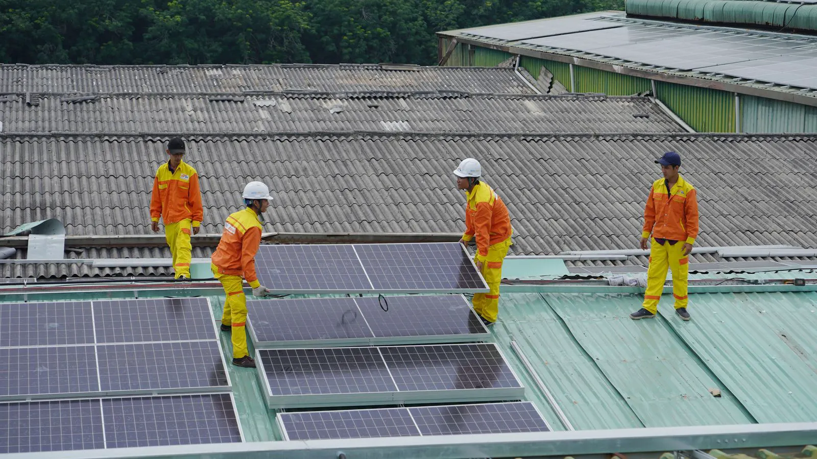
How Roof Uplift Forces Change Racking Structural Design
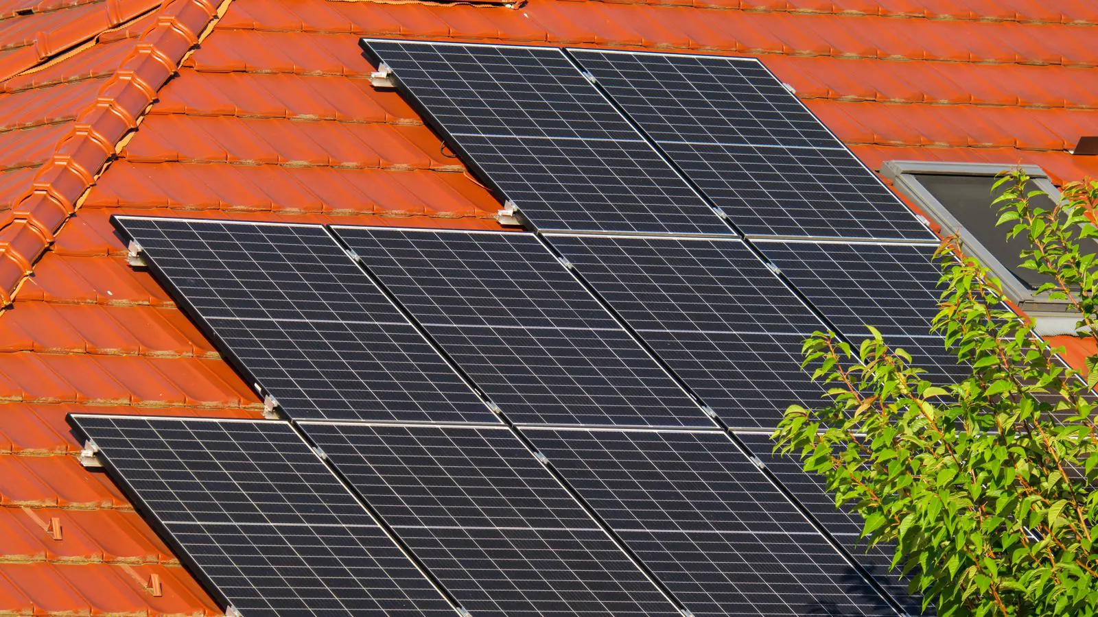
Roof uplift reverses the direction of force on solar racking, pulling panels away from the roof deck. This changes how structural engineers calculate loads and which fasteners, clamps, and tie-downs must be selected for a specific roof assembly.
- Roof uplift reverses the load direction, shifting stress from compression to tension in fastening points
- Anchor selection depends on the roof deck material and the direction of the pull force
- Layout spacing and row spacing directly affect the effective wind pressure on the array
- Engineering calculations must account for both positive and negative pressure zones
- Post-installation inspections should verify that no fasteners have loosened under cyclic loading
What Roof Uplift Actually Means for a Mounted Array
Solar racking is designed to hold panels down against gravity. That is the default assumption in most early-stage planning conversations. But wind does not push from above in a way that simply adds weight. Wind creates suction on the underside of the roof and on the windward face of the array. This suction is roof uplift. It pulls the mounting hardware upward and outward, trying to separate the structure from the roof deck.
The physics is straightforward. When wind flows over a roof edge or a ridge, it accelerates and creates lower pressure on the exposed surfaces. The higher pressure inside the building or on the sheltered side of the panel array pushes against the lower pressure zone. The net force is upward. For a flat roof, this force acts on the entire roof surface. For a pitched roof, the force distribution changes depending on whether the wind hits the windward slope, the leeward slope, or the ridge.
This reversal changes everything about how the structural design works. The fasteners are no longer just holding weight. They are resisting a pull force that tries to rip them out of the deck. The rails and mid-rails must transfer this tension load to the anchors without deforming. The clamps must hold the glass without cracking the panel edge. Every component in the chain must be rated for tension, not just compression.
How Uplift Changes the Load Path
The load path is the route a force takes from the point of application to the structural element that resists it. Under normal gravity load, the path is simple. The glass weight pushes down through the clamps, into the rails, down through the legs, into the anchors, and into the roof deck.
Under roof uplift, the path flips. The wind suction acts on the underside of the glass and the underside of the rails. This force pulls upward through the clamps and rails. The tension travels along the mid-rail and the end rails to the anchor points. The anchors then pull against the roof deck in the opposite direction of gravity.
This means the structural engineer must calculate two separate load cases. The first is the gravity case, where the array weight plus any snow load pushes down. The second is the uplift case, where the wind suction pulls up. The design must satisfy both. A fastener that is perfectly adequate for holding a heavy array down may be completely inadequate for resisting the upward pull. The shear direction changes, and the bearing stress in the deck changes.
How Anchor Type Selection Responds to Uplift
Anchor selection is the first sourcing decision that changes when uplift becomes the dominant load. A lag screw that works well for a flat roof with low wind exposure may fail on a ridge where uplift pressures are highest. The connection must resist a force that tries to extract the fastener from the deck.
The choice of anchor depends on three things. The roof deck material, the thickness of the deck, and the magnitude of the uplift force per anchor. Wood sheathing responds differently to pullout than metal standing seam does. Concrete roof slabs require different anchor types than metal roofing.
A standing seam roof is a common case. The anchors cannot penetrate the seam because that would compromise the waterproofing. The solution is a clip-based system that attaches to the seam without piercing it. These clips rely on friction and mechanical interlock to resist uplift. If the uplift force exceeds the friction threshold, the clip can slip. The structural design must account for this by spacing the clips closer together or selecting a clip with a higher friction rating.
For wood deck roofs, the anchors must resist pullout from the wood fibers. The load path here is tension in the fastener and shear in the wood. If the wood is soft or the deck is thin, the fastener can tear the wood out. Engineers may specify threaded rods with washers that distribute the load over a larger area, or they may require a structural adhesive in addition to mechanical fastening.
How Layout and Spacing Affect the Uplift Load
The physical layout of the array changes the wind pressure the structure must resist. This is where solar wind load interacts with the geometry of the installation.
The effective wind pressure is not uniform across the array. The windward edge of the array experiences higher suction than the center. The leeward edge experiences a different pressure distribution. The spacing between rows changes how wind flows over the array. If the rows are too close, wind accelerates between them, creating higher velocities and higher suction. If the rows are too far apart, each row acts more like an isolated object, which can change the pressure coefficients.
The row spacing also affects the shadowing of the roof deck. In low wind conditions, the panels shade the deck and reduce the local wind speed. In high wind conditions, the panels create turbulence that can increase local pressures. The structural engineer must model these effects using wind load coefficients that reflect the actual spacing and the roof profile.
A common mistake is to treat the array as a single flat plate. That approach overestimates the load on some parts and underestimates it on others. The correct approach is to use a wind tunnel test or a computational fluid dynamics model that accounts for the specific array geometry. The resulting load map is then applied to each anchor point.
How Component Selection Changes Under Uplift
Once the load map is known, the component selection process changes. The clamps must be rated for the tension force at the panel edge. The rails must have sufficient thickness to resist bending and torsion. The legs must be stiff enough to prevent lateral deflection. The anchors must be the right type for the deck.
The clamps are often the first point of failure under uplift. The glass edge is in tension, and the clamp must hold it without cracking. If the clamp is too loose, the glass can vibrate and the edge can chip. If the clamp is too tight, it can crack the glass. The structural design specifies the clamp torque, and the installer must follow it.
The rails must transfer the tension load to the anchors. Thin rails can buckle or deform under the pullout force. The rail cross-section must be sized so that the bending stress stays below the material yield point. The connection between the mid-rail and the end rail is a critical point. If this connection is weak, the rails can separate under cyclic loading.
The anchors are the final link. They must be selected to match the deck and the uplift force. The pullout capacity of the anchor must exceed the design uplift force with a safety factor. The safety factor depends on the local building code and the criticality of the structure. A roof failure can be catastrophic, so safety factors are typically higher for uplift than for gravity loads.
A Worked Example in Plain Words
Consider a pitched roof with a metal deck and standing seam. The array is positioned near the ridge. The wind comes from the south, hitting the south face of the roof. The wind accelerates over the ridge and creates high suction on the north face of the array.
The structural engineer calculates the uplift force at the north edge of the array. This force is higher than the force at the south edge because the north face is in the low pressure zone. The engineer sizes the anchors at the north edge for a higher pullout force than the anchors at the south edge.
The anchor type is a standing seam clip. The clip is attached to the seam without piercing it. The clip relies on friction to resist the upward pull. The engineer checks the friction threshold against the design uplift force. If the friction is not sufficient, the engineer specifies more clips per meter of rail, or selects a clip with a higher friction rating.
The layout is adjusted. The row spacing is increased slightly to reduce the turbulence between rows. This lowers the peak suction on the north face. The anchor spacing is increased to match the new row spacing. The clamps are torqued to the specified value. The rails are checked for bending stress. The whole system is designed to resist the specific uplift load case without any component failing.
After installation, the system is inspected. The clips are checked for slip. The clamps are checked for proper torque. The anchors are checked for tightness. If any fastener has loosened, it is re-torqued or replaced. This inspection is part of the maintenance plan for the array.
How Post-Installation Checks Handle Uplift
Wind events do not all behave the same way. A steady wind is different from a gust. A gust can create a higher peak force than the average wind speed suggests. The structural design includes a safety factor for this, but the physical hardware still experiences cyclic loading.
Over time, the fasteners can loosen. The vibration from wind can work the clamps loose. The thermal cycling can cause the metal rails to expand and contract, which can work the anchors loose. The roof deck can settle, which can change the bearing stress on the anchors.
The post-installation check is a visual and tactile inspection. The installer walks the array and checks each clamp. They check each anchor. They look for signs of movement, such as a lifted seam or a cracked panel edge. They also check for corrosion, which can weaken the fasteners over time.
If a fastener has loosened, it is re-torqued to the specified value. If the fastener is damaged, it is replaced. If the anchor has pulled out of the deck, the deck may need to be repaired. The repair must be done by someone who understands the structural design, because the repair changes the load path.
The inspection should be done after major wind events. It should also be done on a regular schedule, such as once a year. The inspection records should be kept with the structural design documents. This creates a history of the system and helps identify any trends in fastener loosening or deck movement.
How to Source Components for Uplift-Driven Designs
When sourcing components for a project where uplift is the dominant load, the specification must be clear. The engineering drawing shows the load map. The component schedule lists the required rating for each part. The supplier must confirm that the component meets the specification.
The supplier should provide test data for the component. This data shows the pullout capacity of the anchor, the bending capacity of the rail, and the tension capacity of the clamp. The test data must be from a recognized testing body. The test conditions must match the service conditions.
The supplier should also provide installation instructions. The installation torque for the clamps, the spacing for the anchors, and the method for attaching the clips must be specified. The installer must follow these instructions exactly. A deviation in installation can invalidate the design.
The structural engineer reviews the supplier’s documentation before the components are ordered. If there is any discrepancy, the engineer issues a change order. The components are not shipped until the engineer approves the final selection. This review step catches errors before they become field problems.
The final step is the installation. The installer follows the drawing and the installation instructions. The inspector checks the work as it is completed. The system is then in service, ready to handle the roof uplift forces for the life of the array.
Frequently asked questions
Can a solar array be designed to resist roof uplift if the roof deck is old or damaged?
The deck must be structurally sound before the array is installed. If the deck is damaged, it must be repaired first. The structural design assumes a sound roof deck.
How does the roof pitch affect the uplift force on the array?
The roof pitch changes the pressure distribution. Steeper roofs can experience higher suction on the leeward face. The structural engineer must model the specific pitch to get the correct load.
Is the wind load the same for every anchor on the array?
No. The wind load varies across the array. The anchors at the windward and ridge edges experience different forces than the anchors at the leeward edge. The load map shows the variation.
Can the array be moved to a location with lower wind exposure to reduce uplift?
Yes. Moving the array away from the ridge or to a more sheltered part of the roof can reduce the uplift force. The structural engineer must re-calculate the loads for the new location.
What happens if the wind exceeds the design value?
The safety factor in the design provides some margin. If the wind exceeds the design value significantly, the components may fail. The structure is designed for the expected wind range, not for unlimited wind.